

consiLetter 1
consiletter 1
Safeguarding of a supply line for pressurized air
As in many of our customers’ laboratories, the apparatuses in the laboratories of consilab have to be supplied with technical gases, too. In most of the cases, the tasks of pressure vessel safety are similar and the questions recur. For this reason, the assembly in the consilab laboratory shall be described as an example.
Commonly, compressed gas cylinders can only be operated when equipped with a pressure reducing device. But what is going to happen, if the pressure reducing device of a new, completely filled gas cylinder is damaged or fully opened when connected to the laboratory equipment? The total pressure of the cylinder could propagate via open pipelines into the apparatuses and eventually destroy those. To prevent this, a safety valve is to be installed into the feed line, to set the maximum pressure of the system to the maximum allowable pressure of the connected apparatuses.
The sizing of safety valves is part of the range of services offered by consilab. First of all, the mass flow rate to be discharged has to be calculated. This is the mass flow rate of gas which can flow from the gas cylinders into the connected apparatuses. Basis of the calculations are the pressure difference between maximum pressure in the gas cylinder and the set pressure of the safety valve or the maximum allowable working pressure of the apparatus. The geometric assembly of the feed pipe (diameter, bends, length of pipe from pressure source to the place where the safety valve is connected) can be taken into account for the calculation. In many cases the seat area of the pressure regulator, which could open completely due to a full break of the membrane, is most relevant for the result.
In the next step a safety valve has to be chosen. The dischargeable mass flow at set pressure has to be equal or higher than the mass flow to be discharged which was calculated in the first step. On the other hand, the safety valve should be as small as possible, since the gas feed lines are usually very small and there is not much space in a fume hood. But not every safety valve is applicable to reliably venting the required gas mass flow.
Because of the high pressure difference of the compressed gas cylinder (300 bar at consilab) and the apparatus (30 bar at consilab) and the relatively low pressure difference between set pressure and ambient pressure, the required venting area is accordingly high.
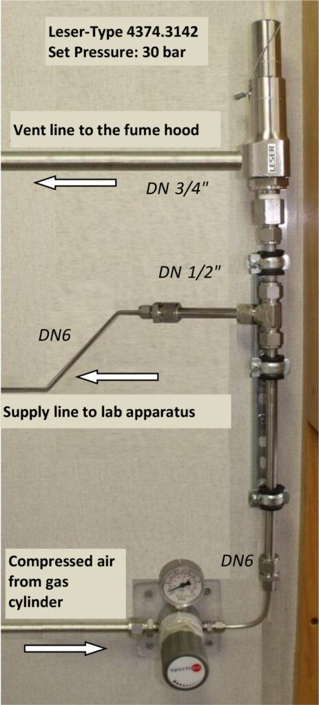
In the actual case a safety valve by Leser, size ½”/ ½”, type 437, is sufficient to protect the feed line in size DN6. The easiest way to connect the safety valve to the feed line seems to be to insert a branch tee and expand the line behind it to the size of the safety valve inlet. However this is not permissible. Standards like ISO 4126 regulate that there must not be a diameter smaller than the safety valve inlet diameter in the line between the room to be protected and the safety valve itself. Additionally, the pressure losses in the line to the safety valve are to be restricted to 3% of the set pressure. To meet these criteria, the diameter of the feed line has to be expanded to the safety valves inlet size before the branch tee. An example of an ideal assembly for this task is shown in the photo.
If we can support you at a similar task, please feel free to contact us. Our experts will be happy to place our services at your request.